This article is intended to provide you with the knowledge to confidently build your camper van electrical system from scratch. My goal is to make this article easy to understand and straight to the point. This will not be a comprehensive electrical bible that floods your brain with every possible electrical component and configuration under the sun. Instead, I will only provide you with the descriptions, components, and configurations you need to get the job done right.
With that being said I don’t want this to undermine the seriousness of performing electrical work. ELECTRICITY IS DANGEROUS!!! Before attempting to build your system make sure you know what you’re doing. As you progress in the build, always double check all of your connections and never take short cuts.
If you still feel lost after reading this article, you can always reach out for a consultation with our team!
Now let’s get to it!
Contents
How Does a Camper Van Electrical System work?
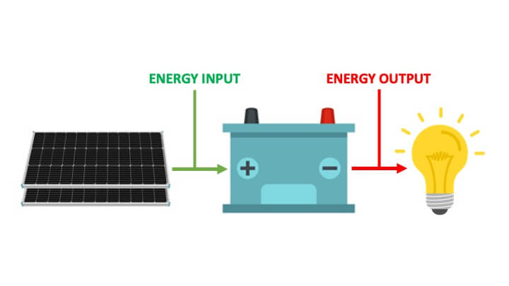
Camper van electrical systems can be boiled down to three categories: Chargers, Batteries and Loads.
Chargers:
Chargers capture the energy required to operate your van. These are components like solar panels, DC-DC Chargers (alternator), and shore power (grid).
Battery Bank:
Batteries are the storage unit for your vans electrical system. The batteries take in energy from the charging sources and store it until its needed by the loads downstream.
Loads:
Loads are the devices and appliances in your van. Anything that requires electrical energy to operate is considered a load.
Electrical Terminology: Volts, Amps, and Watts
This is the language of electricity! These three simple definitions will create the foundation of the knowledge you need to design and build your camper vans electrical system.
Volts (V):
Voltage is the force that pushes a charge through a wire. In a camper van there are two voltages that we’ll use: 12V and 120V. 24V & 48V systems exist, but I won’t discuss those here.
Amps (I):
Electrical current is measured in amps. There are two types of current in a camper van: Direct Current (DC) and Alternating Current (AC). Direct current flows through a circuit in one direction, while alternating current flows in two (alternating) directions.
Watts (P):
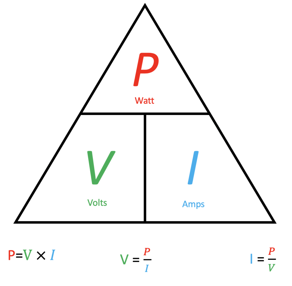
A Watt is a measure of power. A watt describes the relationship between voltage and current. You can calculate watts by using Watts law: Watts= Volts X Amps. This single formula will solve most of your camper van electrical problems.
Below I’ve included the “power triangle”, which is a simple visual method for solving for different variables in this formula. To use the triangle simply put your finger over the unit that you would like to solve for.
Don’t get too hung up on this section yet. It will begin to make more sense after I discuss the different electrical components later in the article. I’ll use this formula in examples later on to help you better understand it’s application.
Electrical Circuits: Series vs. Parallel
There are two types of circuits that you’ll use when building your van: Series and Parallel.
Series Circuits
Description: A series circuit only provides one path for current to flow.
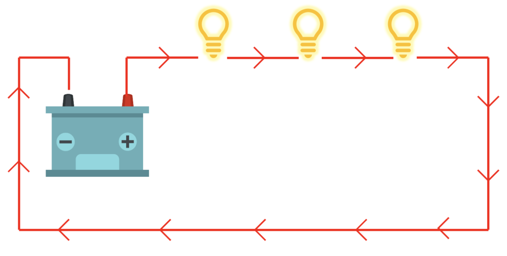
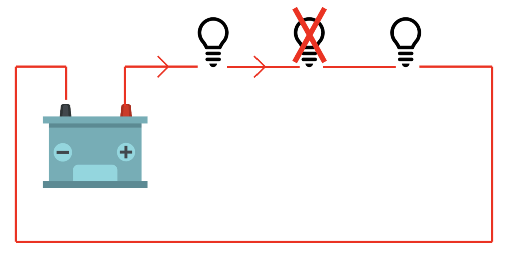
Effect on Loads: If one load (i.e lightbulb) fails then all of the lights go off. A good example of this is when a single bulb on a string of Christmas lights fails; the entire string goes out.
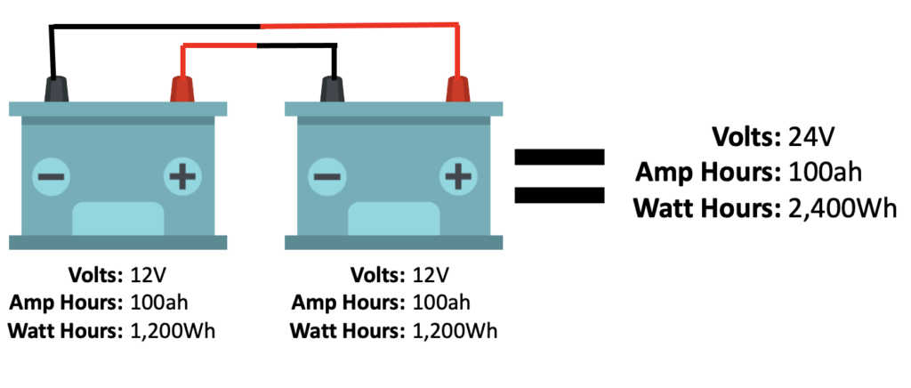
Effect on Power Sources: Batteries or chargers connected in series add their voltage and the current remains the same.
Parallel Circuits
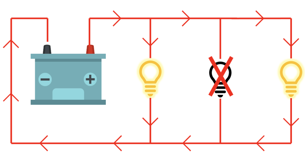
Description: A parallel circuit provides alternate paths for current to flow.
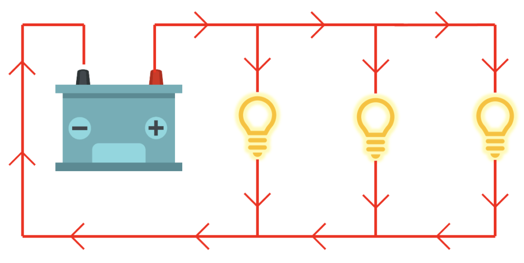
Effect on Loads: If one load (i.e lightbulb) fails then the remaining lights stay on because the current flows between each branch.
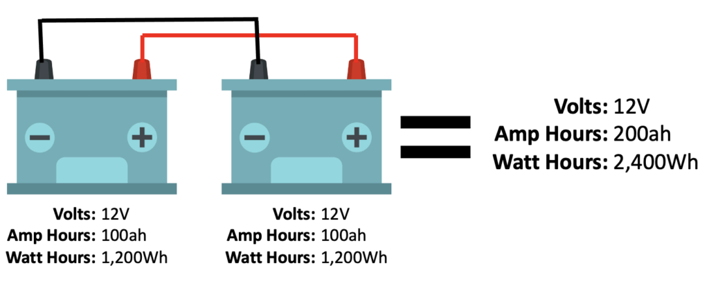
Effect on Power Sources: Batteries or chargers connected in parallel add their current and the voltage remains the same.
Required Components for your Camper Van Electrical System
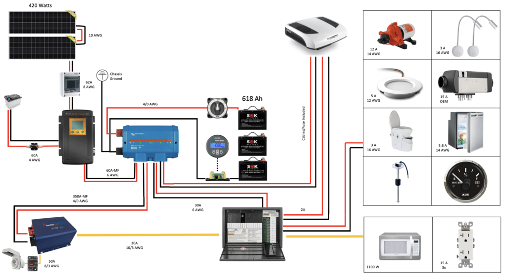
The overall layout of the electrical system can look intimidating, but there’s really only three components. The 3 key components of a camper van electrical system are: Batteries, Chargers, and Distribution/Fusing. We’ll break these systems down below.
Batteries
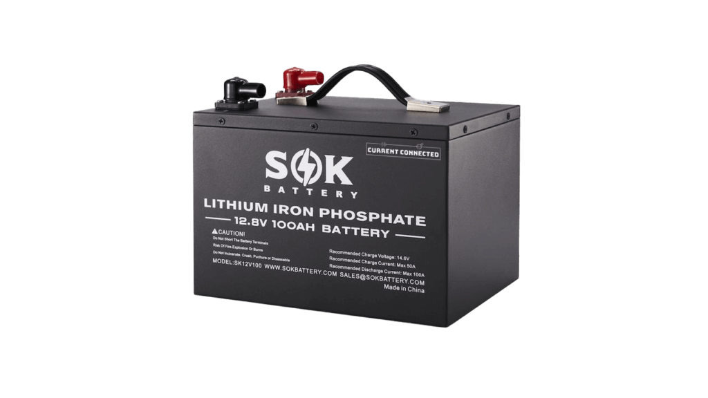
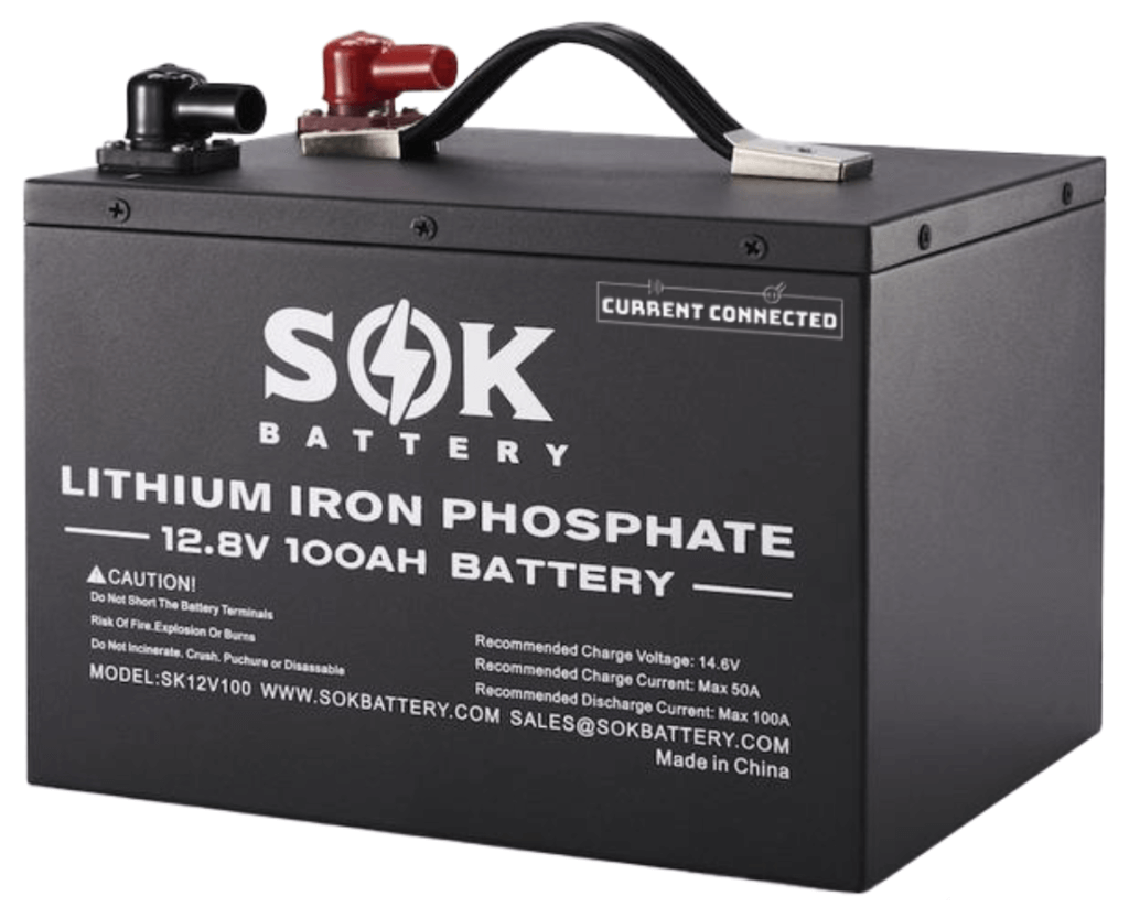
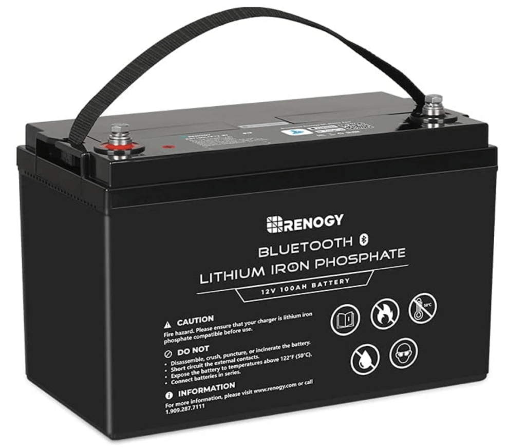
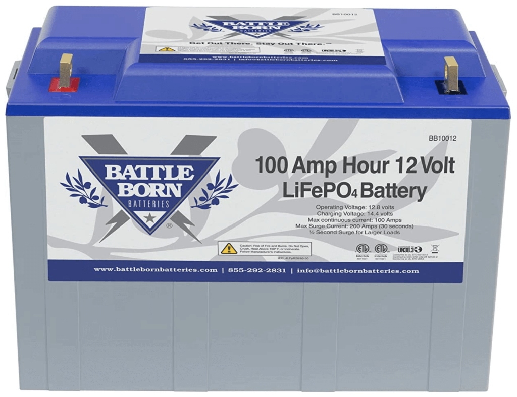
Batteries come in many shapes, sizes, chemistries, and voltages. For the sake of keeping things simple I’m only going to discuss two different options: 12v Lithium Iron Phosphate (LiFePO4) and 12v Deep Cycle Absorbent Glass Mat (AGM). Below I’ll compare the key stats of a 12v 100ah AGM and LiFePO4 battery.
Full Disclaimer: I have only used LiFePO4 batteries in my builds. The price of LiFePO4 batteries has decreased, and they’ve become much safer to use over the years. Their advantages far exceed the additional cost when compared to AGM. If you’re going to splurge on any part of your build this is where I recommend doing it.
√ Price: $199
Price: $599
Amp Hour: 100ah
Amp Hour: 100ah
Discharge Floor: 50%
√ Discharge Floor: 10%
Max Charging Current: 30A
√ Max Charging Current: 50A
√ Charge Temperature: 5-104°F
Charge Temperature: 32-140°F
Cycle Life: 500
√ Cycle Life: 4000-8000
Weight: 64 lbs.
√ Weight: 28 lbs.
Lets breakdown that comparison:
Amp Hour:
The amp hour (ah) rating is a rating used to describe the batteries capacity in amps. A 100ah battery should be able to power a 100 amp load for 1 hour.
Discharge Floor:
The discharge floor is the capacity of usable energy in the battery. If you discharge the battery past the floor rating it will damage it and reduce its total life span. This is arguably the biggest difference between AGM and LiFePO4 batteries. AGM batteries are only capable of discharging 50% of their rated amp hour capacity before damage occurs; while LiFePO4 can discharge 90%-100% of the capacity. For example:
If you decide you need a battery bank of 200 usable amp hours that would require 4x 100ah AGM batteries OR 2x 100ah LiPO4 batteries. The price difference really becomes negligible when you consider this fact. Additionally, van builds are all about making the most efficient use of your space. The additional AGM batteries take up more space than their LiFePO4 competitor.
Maximum Charge Current:
This is the rate in amps that you can safely recharge your batteries.
Discharge Temperature:
This is the temperature range that the battery can safely discharge.
Charging Temperature :
The temperature range that you can safely recharge the battery. Lithium batteries take a loss here, but let me explain why that isn’t that big of a deal. THEY MAKE HEATED BATTERIES. The heated batteries are a little more expensive, but they could be a savior in cold climates. We use non-heated batteries and have never had an issue (And we chase snow during the winter).
Cycle Life:
This is the amount of times you can discharge/recharge your battery. 100-10% is one full cycle for the lithium battery listed above.
Weight:
I think this one is obvious. The weight of your van build is super important to the overall performance of the vehicle. Using lithium allows you to shave quiete a few pounds off your build.
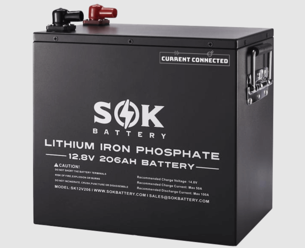
Battery Recommendations (100ah):
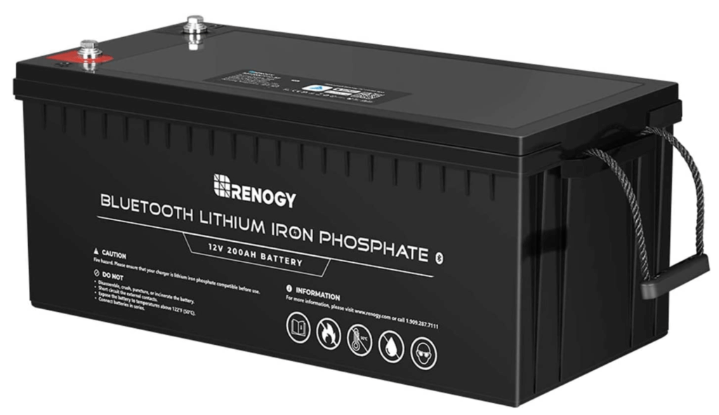
Battery Recommendations (200ah):
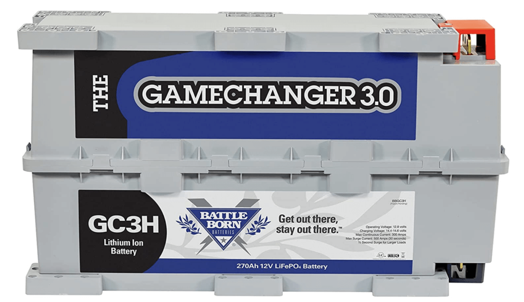
Battle Born (270ah)
Key Specs
• Rec. Charge Current: 150A
• Rec. Discharge Current: 300A
Camper Van Charging Sources
There are 3 main charging sources for your vans batteries: solar (the sun), the alternator (DC-DC), and shore power (Grid). I’ll go into more detail below.
Solar Power
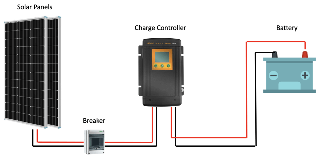
Solar power is converting the sun’s energy into usable electric power through the use of solar panels and a solar charge controller. There’s a lot to cover in this section, but the overall application is simple. It looks something like this:
Solar Panels
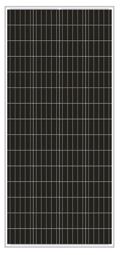
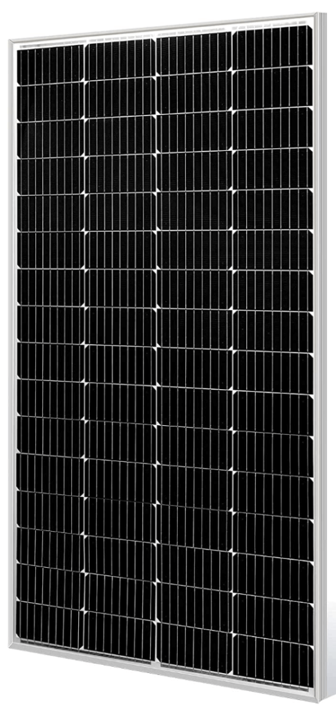
Solar panels come in many shapes and sizes, and it can be a bit overwhelming when you begin shopping for your own panels. However, there’s only a few things you need to look at that will help drastically narrow your search: Monocrystalline vs. Polycrystalline, Panel Dimensions, and Configuration.
Monocrystalline or Polycrystalline?
Monocrystalline cells are more efficient than poly. That’s really all you need to know.
Solar Panel Dimensions
This is obvious, but it’s important to verify how much space you have available on your roof, and to order your solar panels accordingly. You’ll likely be competing for space with things like a roof fan, air conditioners, or even a rooftop deck. Planning the layout for the top of your van is equally as important as planning for the interior build. You can buy panels of all varying sizes to fit around those obstacles, but it’s VERY important that you understand how to configure that layout.
Solar Panel Configuration
The configuration of your solar array can be altered in two ways: wiring and panel wattage variation. Remember earlier when we covered Watts Law and the power triangle? Well now we get to apply that knowledge to our design. Remember, watts (W) are a measure of power that describe the relationship between voltage and current.
Solar Panel Wiring
There are three ways to wire solar arrays: in series, in parallel, or series-parallel.
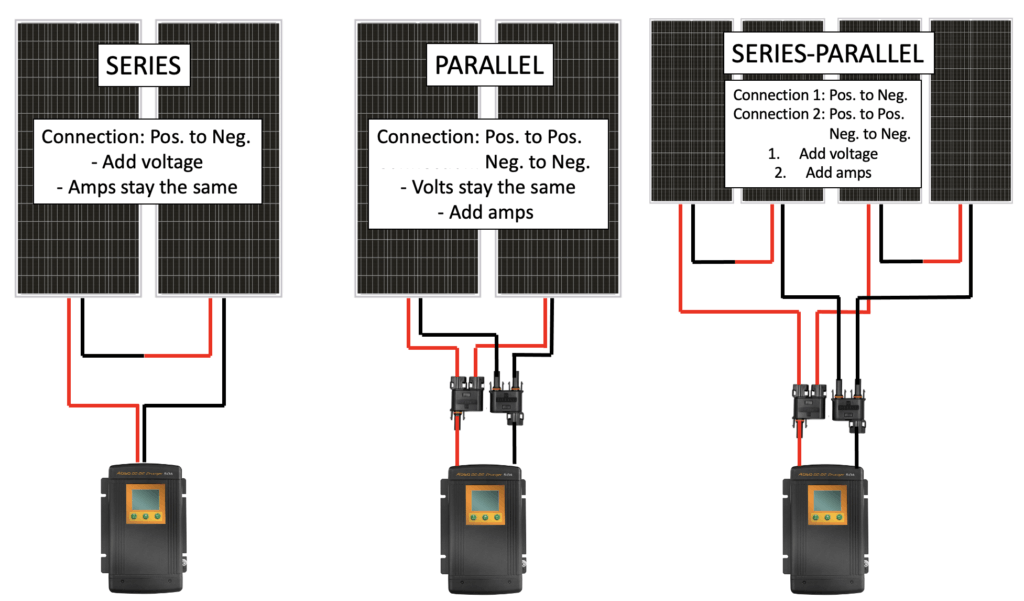
I’ll discuss the application, effect and pros/cons below. It’s important to note that regardless of the configuration your system is limited to the total wattage of the array. Producing a higher current or voltage can be advantageous in different scenarios, but it will never result in more power capacity. A 400W solar array can only produce a maximum of 400W. However, a 400W solar array can produce less than 400W if configured incorrectly.
When solar panels are sold they’re typically listed by their wattage and voltage ratings (ex. 100W 12V panel). The voltage of the solar panel does not have to match the voltage of your battery bank. Panels advertised as 12V actually produce a higher voltage, and that rating is called the Voltage at max power or Vmp.
You want to use the Vmp rating when doing your solar calculations. You can use any voltage panel as long as it does not exceed the voltage input rating on your charge controller because =the charge controller takes that voltage in and optimizes it for your batteries. However, it is necessary that your charge controllers output voltage matches the voltage of your battery bank. That was definitely confusing for me at first. You just need to remember that the charge controller is the mediator between your solar panels and your battery bank.
Let’s look at some examples…
Series Connection
Application: + to – connection
Effect: Solar panels connected in series add their voltage while their amps remain the same.
Pros: This configuration keeps the amperage low and allows for the use of smaller wires. It’s a great way to save some money.
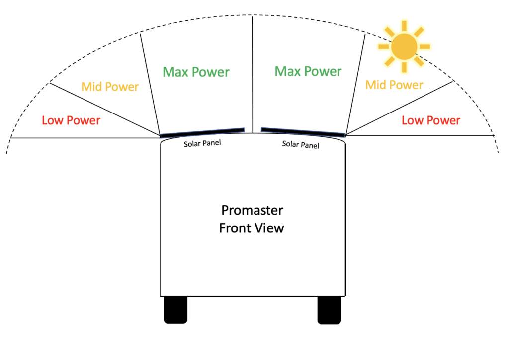
Cons: The solar panels are dependent on each other. This means that if one panel stops working, then no power is delivered. If one panel is partially shaded, both panels outputs are significantly reduced. Panel mounting orientation is also more important when wired in series. Solar panels produce the most power when the sun is directly above them.
I learned this lesson on a previous build. I mounted two solar panels on the roof of a Promaster parallel to each other in a front to back orientation. This meant that each panel was ever so slightly tilted in opposite directions due to the small curve on the Promasters roof (shown below). The curve is so small that I assumed it would not cause an issue. I was wrong.
Later in the build I noticed that the solar output was below what I had anticipated. It ended up being because the whole arrays output was limited to whichever panel was receiving the least amount of sun. This was most noticeable in the mid-low power times of the day. During low angle sunlight the panel receiving the least sunlight determined the max power output of the array. I swapped to a parallel configuration and resolved this issue. That doesn’t mean that a parallel connection is better, it was just more efficient for this configuration.
Example: My personal van uses 420W of solar so i’ll use a similar example. For simplicity sake I rounded off all of the numbers to make them easier to work with. I refer to the units as you will see them on a technical data sheet for a solar panel.
Pmax: (Power maximum) This means maximum power output. 200 watts in our example.
Vmp: (Voltage at maximum power) This refers to the maximum voltage produced at Pmax. 20 volts in our example. It’s worth mentioning that this panel is advertised as a 12V panel. The panel’s advertised voltage is not the same as its Vmp rating. You can absolutely use a 24V panel to charge a 12V battery as long as you’re using a 12V charge controller. This works because the charge controller regulates the voltage before going to the battery.
The main spec difference between panels advertised as 200W 12V vs. 200W 24V is their amperage (Imp) rating. A panel with a higher voltage will produce a lower amperage. However, both panels will only produce 200W of power. They’re the same, but different.
Imp: (Current at maximum power) This refers to the current produced at maximum power.
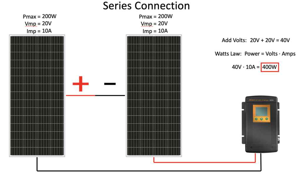
Answer: At maximum power of 400W this configuration produces 40 volts and 10 amps.
Parallel Connection
Application: + to + and – to – connection
Effect: Solar panels connected in parallel add their amperage while the voltage remains the same.
Pros: This configuration allows the panels to work independently of each other. That means that that if one panel stops working, the other will continue to deliver power. This also lessens the negative effects of partial shading.
Cons: This configuration produces a higher current which will require larger wires and could get expensive. This set up also requires the use of MC4 branch connectors. These are an additional cost (though minor).
Example: My personal van uses 420W of solar so i’ll use a similar example. For simplicity sake I rounded off all of the numbers to make them easier to work with. I refer to the units as you will see them on a tech sheet for a solar panel.
Pmax: (Power maximum) This means maximum power output. 200 watts in our example.
Vmp: (Voltage at maximum power) This refers to the maximum voltage produced at Pmax. 20 volts in our example.
Imp: (Current at maximum power) This refers to the current produced at maximum power.
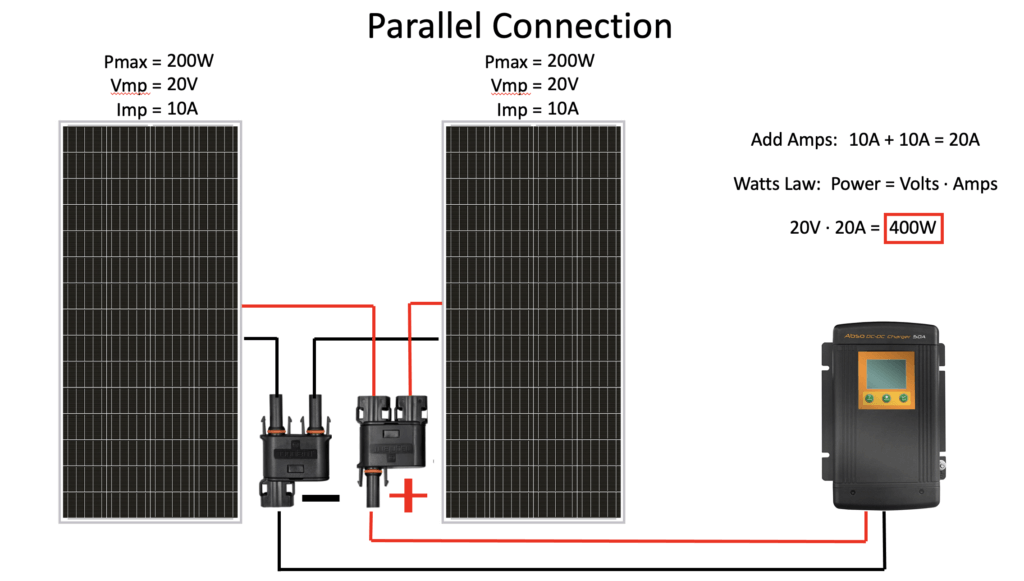
Answer: At maximum power of 400W this configuration produces 20 volts and 20 amps.
Series-Parallel Connection
Application: Our example will use 4x 100W panels. 2x pairs of 2x panels will connect in series, and both pairs will be connected in parallel.
Effect: Solar panels connected in series-parallel use the same rules as mentioned above.
Pros: This configuration allows one pair of the panels to work independently of another pair. That means that that if one pair of panels stops working, the other will continue to deliver power. This also lessens the negative effects of partial shading. The main advantage of this configuration is that it can allow for unique configurations. More on this in the next section.
Cons: It’s more complex.
Example: My personal van uses 420W of solar so i’ll use a similar example. For simplicity sake I rounded off all of the numbers to make them easier to work with. I refer to the units as you will see them on a technical data sheet for a solar panel.
Pmax: (Power maximum) This means maximum power output. 100 watts in this example.
Vmp: (Voltage at maximum power) This refers to the maximum voltage produced at Pmax. 20 volts in our example.
Imp: (Current at maximum power) This refers to the current produced at maximum power.
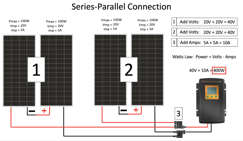
Answer: At maximum power of 400W this configuration produces 40 volts and 10 amps.
Overview:
Series
Application: – to + connection
Effect: Add voltage, amperage stays the same
Pro’s: Keeps amperage low to allow for smaller wires
Con’s: Panels are dependent on each other
Parallel
Application: + to + and – to – connection
Effect: Add amperage, voltage stays the same
Pro’s: Panels work independently of each other
Con’s: Higher amperage could require larger wires from panels to controller
Series- Parallel
Application: Two pairs of panels in series, both pairs wired together in parallel
Effect: Same rules apply to the series vs. parallel pairs
Pro’s: Allows for unique designs with multiple panels
Con’s: More complex
Mis-Matched Panel Wattages
There’s a chance that your solar array could include a variety of different wattage panels. Usually this is needed when you’re placing solar panels around the other objects on your roof (roof fans, air conditioners, roof decks… etc.). You can significantly impact the performance of your solar array by doing this if you’re not careful. Let’s take a look…
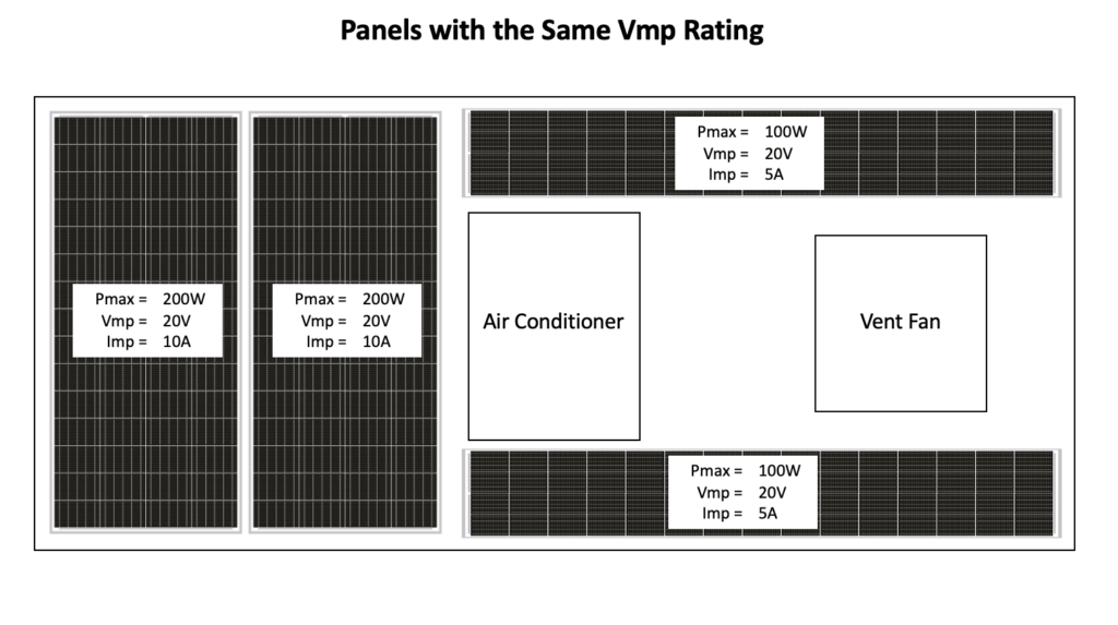
Series
When mismatched panels are wired in series their amperage is limited to the lowest Imp rating.
Add Voltages: 20V+20V+20V+20V= 80V
80V • 5A = 400W
Result: By wiring the array in series we get a maximum power output of 400W. This configuration makes the additional panels useless.
Parallel
When mismatched panels are wired in parallel their voltage is limited to the lowest Vmp rating.
Add Amperages: 10A+10A+5A+5A= 30A
20V • 30A = 600W
Result: By wiring the array in parallel we get a maximum power output of 600W. This configuration maximizes the arrays out.
Series- Parallel
The respective rules apply to each pair. Matching panels are paired in series.
Pair 1: 20V+20V= 40V
Pair 2: 20V+20V= 40V
Add Amps: 10A+5A= 15A
40V • 15A = 600W
Result: By wiring the array in series parallel we get a maximum power output of 600W. This configuration maximizes the arrays out.
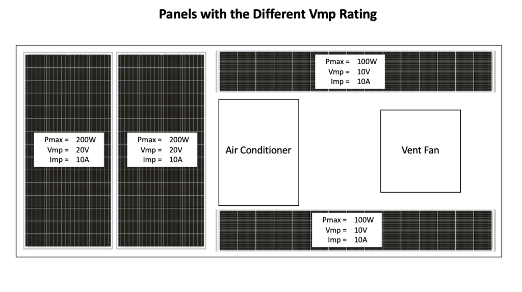
Series
When mismatched panels are wired in series their amperage is limited to the lowest Imp rating.
Add Voltages: 20V+20V+10V+10V= 60V
60V • 10A = 600W
Result: By wiring the array in series we get a maximum power output of 600W.
Parallel
When mismatched panels are wired in parallel their voltage is limited to the lowest Vmp rating.
Add Amperages: 10A+10A+10A+10A= 40A
10V • 40A = 400W
Result: By wiring the array in parallel we get a maximum power output of 400W. This configuration makes the additional panels useless.
Series- Parallel
The respective rules apply to each pair. Matching panels are paired in series.
Pair 1: 20V+20V= 40V
Pair 2: 10V+10V= 20V
Add Amps: 10A+10A= 20A
20V • 20A = 400W
Result: By wiring the array in series parallel we get a maximum power output of 400W because we’re limtied by the pair with the lowest voltage. This configuration makes the additional panels useless.
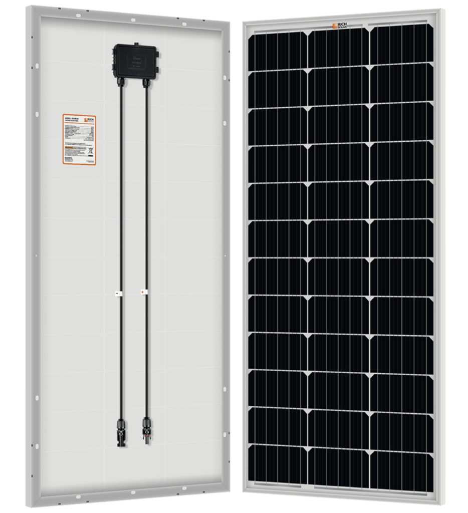
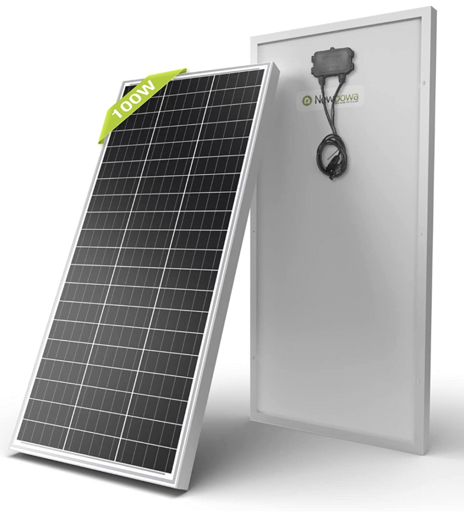
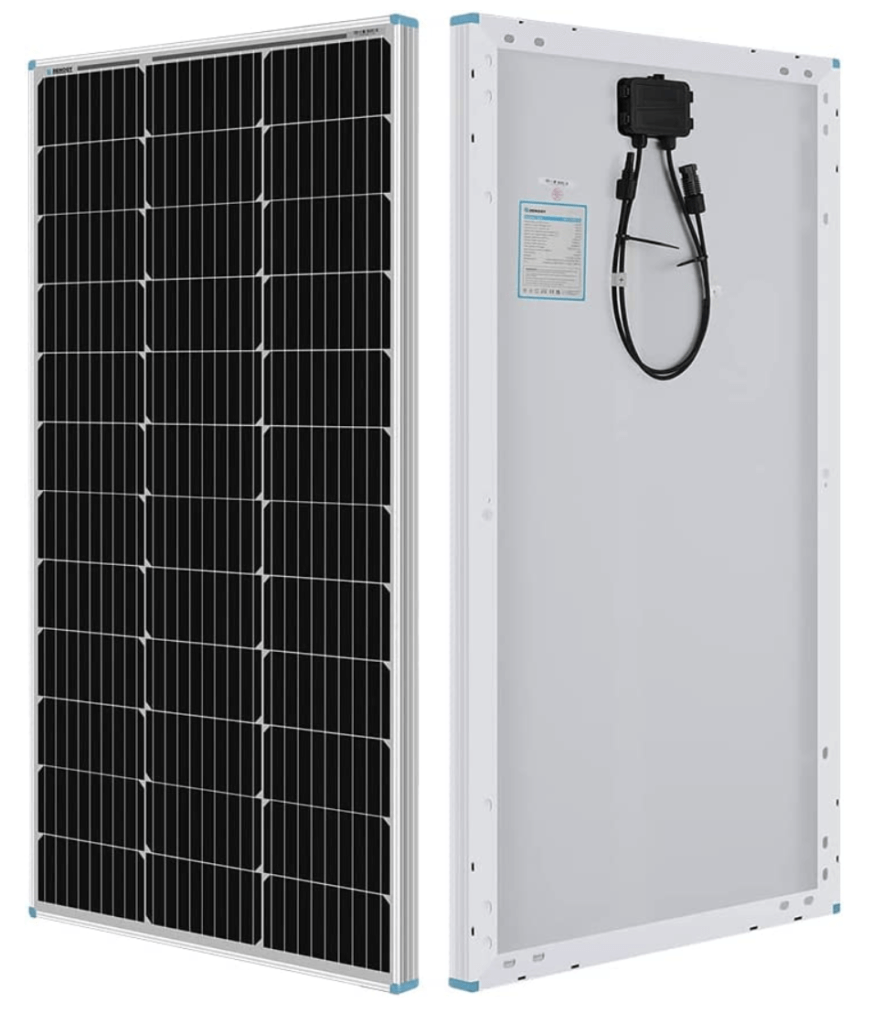
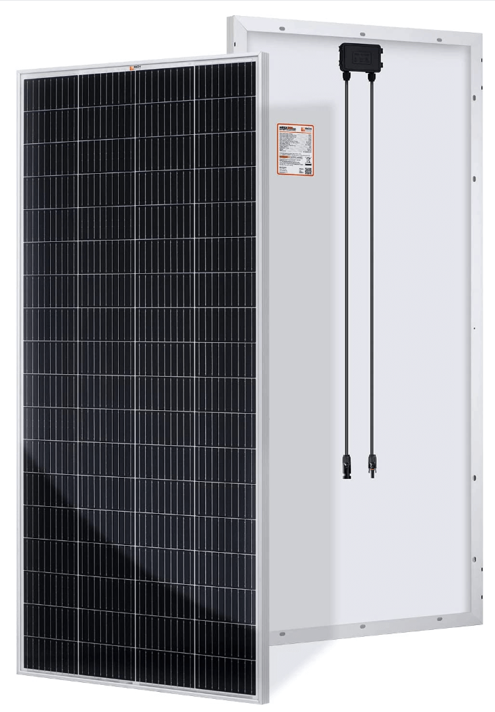
Solar Panel Recommendations
Okay, so that was a LOT of information to take in at once. I hope that you were able to easily understand how different wiring and panel size configurations can affect the overall output and efficiency of your array, Now none of this matters if you buy solar panels that don’t work well in the first place. Below are my three recommendations for solar panel manufacturers.
12V Panels
24V Panels
Solar Charge Controllers
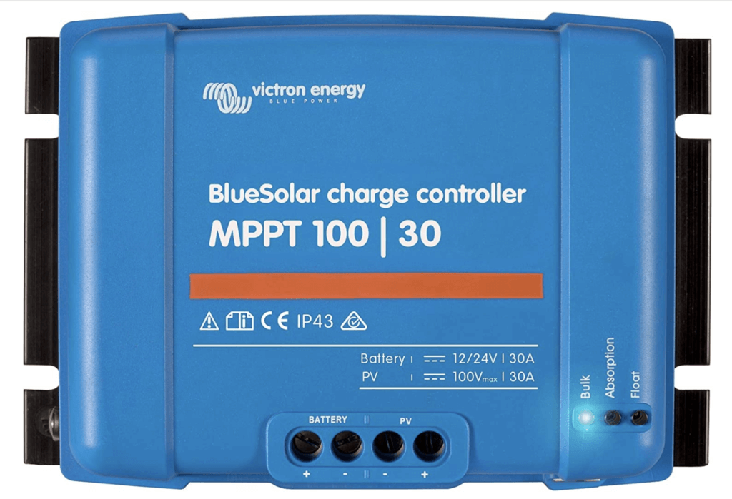
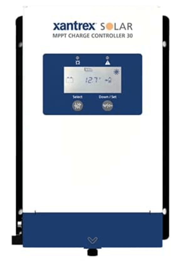
Solar charge controllers are the mediators between your solar array and your battery bank. They take the high voltage power coming from the panels and optimize it for your battery bank.
There are two types of charge controllers: Pulse Width Modulation (PWM) and Maximum Power Point Tracking (MPPT). These are two very different technologies that have the same goal; That is to regulate the power coming from the solar panels to charge your batteries correctly (Yes, there’s a correct way). Without getting into the weeds (and there’s a lot of weeds here) know that MPPT charge controllers are more efficient overall. While MPPT controllers do cost more money their benefits outweigh their additional cost thus that is what I recommend.
When shopping for charge controllers you want to look at two types of ratings: Inputs and Outputs. Input ratings tell you how much current and voltage the controller can take in from your solar panels. Output ratings tell you the the maximum current and voltage that will be delivered to your batteries. It’s vital that your charge controller meets the input demands from your solar array or else you’ll fry this not so cheap component.
Below is a section of the spec sheet for the Kisae DMT 1250 (My current controller) with the critical specs. circled in red. We’ll use these specs in an example below.
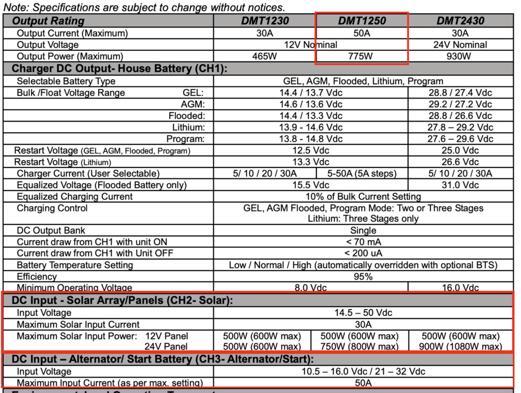
I personally use the Kisae DMT 1250. I chose this controller because at the time of my build it was the only controller on the market that was a MPPT and DC-DC charger in one unit. DC-DC charging is charging from the vehicles alternator. This simplified things when designing the electrical box and it made the overall installation much easier.
So what do these specs mean?
1. The first output rating circled is the units maximum amperage, voltage, and power output.
2. The second input rating circled is the solar array maximum amperage, voltage, and power input.
3. The third input rating circled is the alternator maximum amperage and voltage input.
We’re going to utilize the solar panel configuration knowledge we learned above to ensure that are panel output stays within the acceptable limits of our charge controller.
Here’s what that looks like with 12V panels:
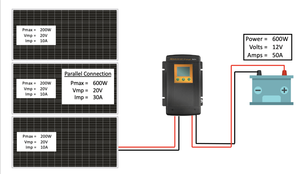
Explanation: To keep the array from exceeding the voltage input maximum (50V) I wired this array in parallel. You can see the effect that the charge controller has on the incoming voltage and current. The solar panels produce a maximum of 30A at 20V then the charge controller works it’s magic and outputs 50A at 12V to our battery bank.
Solar Input
600 Watts
20 Volts
10 Amps
Charger Output
600 Watts
12 Volts
50 Amps
So remember that overdrive feature I was talking about? Let’s take a closer look at that by using 24V panels. Remember, the main difference between 12V and 24V panels is that 24V panels produce a higher voltage and lower current. Their overall power output is the same:
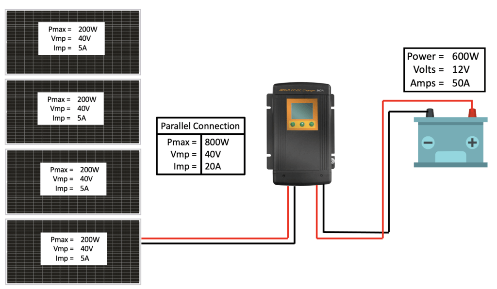
Explanation: To keep the array from exceeding the voltage input maximum (50V) I wired it in parallel. You can see the effect that the charge controller has on the incoming voltage and current. The solar panels produce a maximum of 20A at 40V then the charge controller works it’s magic and outputs 50A at 12V to our battery bank.
You’ll notice that in this example the solar array puts out more power (watts) than the controller can deliver. This extra power does not damage the controller it “Puts it to the side” essentially. This is beneficial because on cloudy days the additional power in the array will help keep the charge controller running at maximum output. As far as I know this is the only charge controller on the market that is capable of this function.
Charge Controller Review
- MPPT controllers are more efficient than PWM controllers.
- Solar charge controllers are responsible for converting the power from your solar panels into usable energy for your battery bank.
- Ensure your solar charge controllers input rating can accommodate your solar arrays max power output.
- Ensure the controllers output voltage matches your battery banks voltage
Recommended Charge Controllers (No DC-DC Charging)
Recommended Charge Controllers (With DC-DC Charging)
DC-DC Chargers (Alternator)
Charging from your alternator is a great way to charge your batteries quickly while driving to your destination. Depending on your needs this form of charging could completely replace solar. There’s multiple ways that this can be accomplished but i’m only going to discuss my preferred methods: with a DC-DC charger or a dual alternator set up.
DC-DC Chargers
DC-DC Chargers work by using the excess power from your vehicle’s starter battery and passing it to your house battery bank when the car is running. These chargers only pull power from the starter battery when needed, and they deliver the charge based on your house batteries charging profile needs.
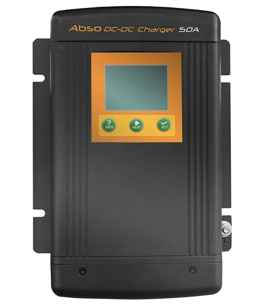
Recommended DC-DC Chargers
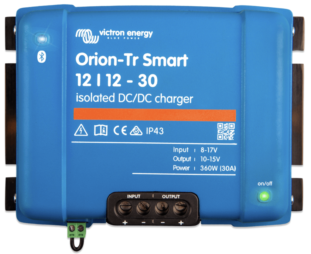
Victron Orion
Key Specs
• 18A & 30A Options
• Bluetooth Built-In
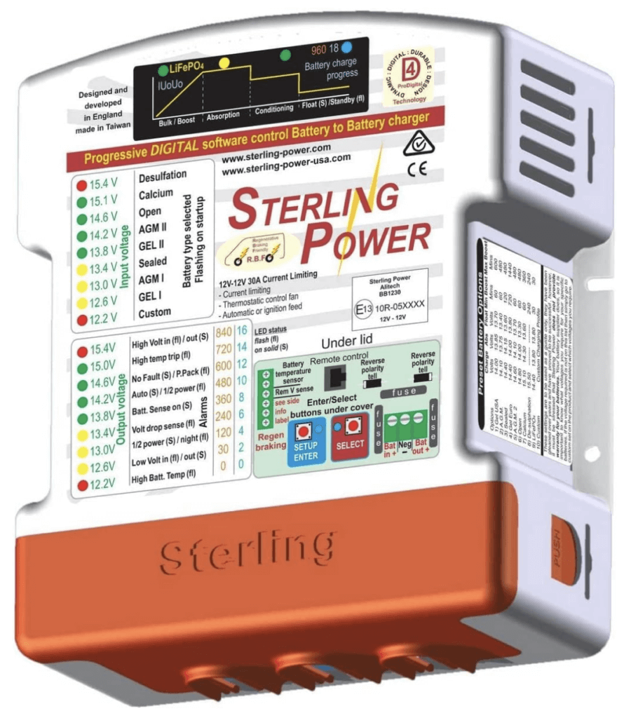
Sterling Power
Key Specs
• 30A & 60A Options
• Remote Control Option
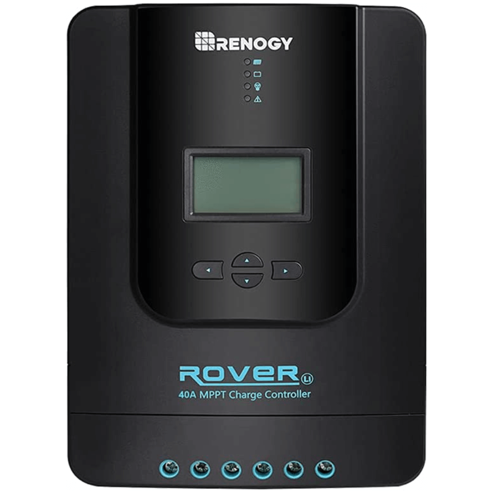
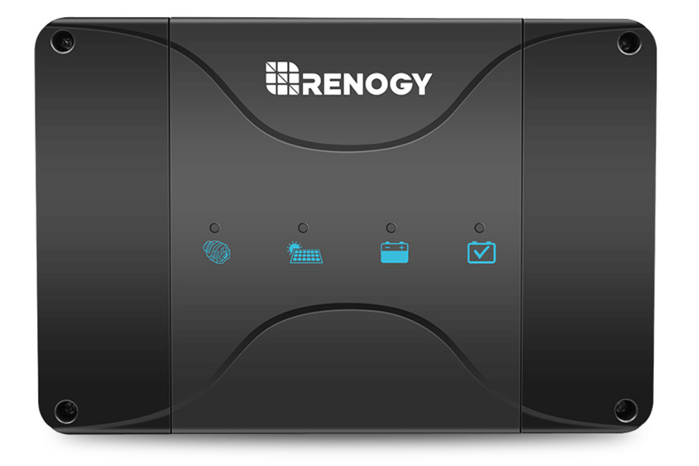
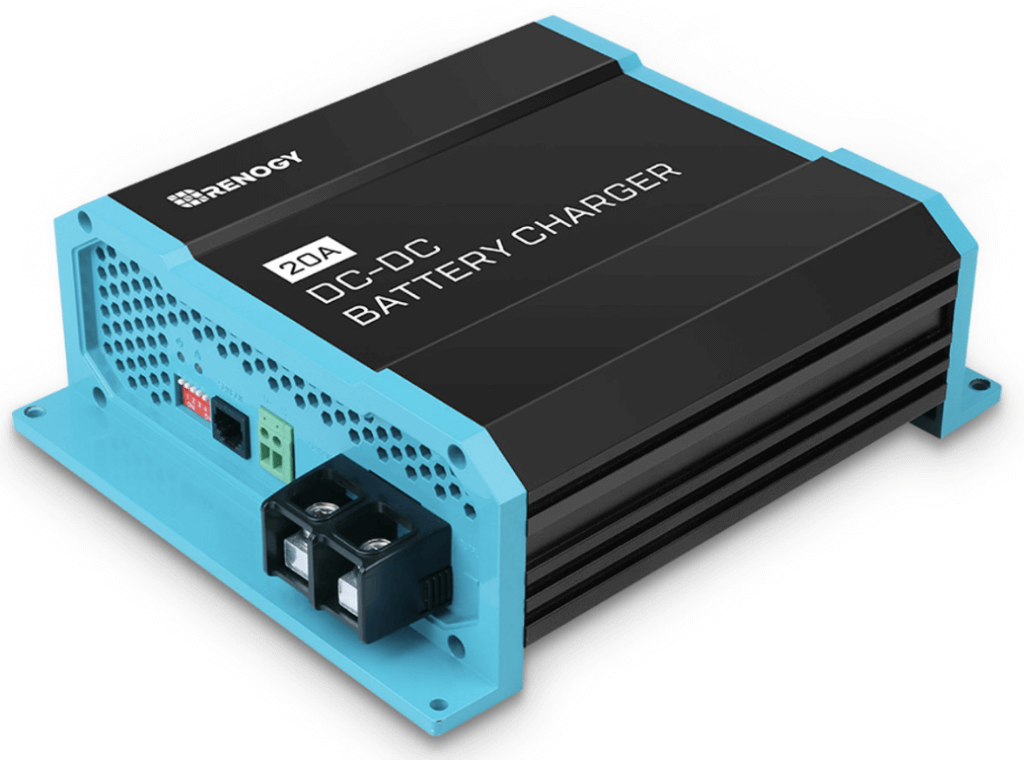
Renogy
Key Specs
• 20A, 40A, & 60A Options
• No Bluetooth
Combined DC-DC/MPPT Charger
Dual Alternators
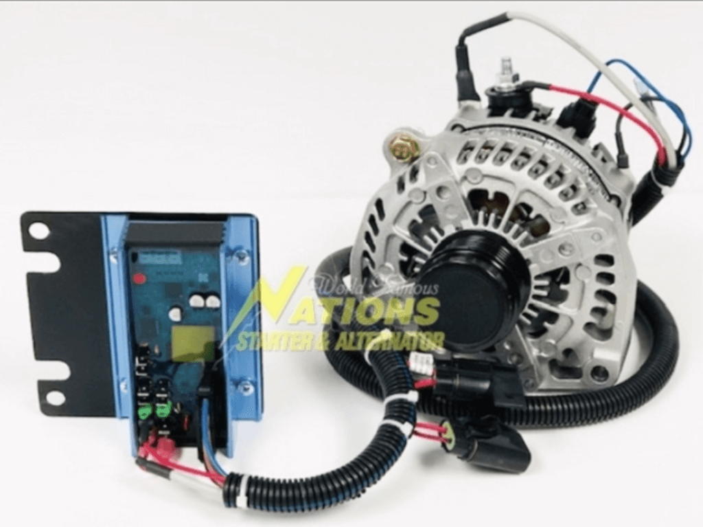
A dual-alternator setup is advantageous because it allows you to harness the full power of the dedicated alternator to charging your house battery bank. It also lessens the strain on the vehicles factory alternator.
This option is pricey, but it has the ability to supercharge your charging capabilities. To my knowledge the only company that produces a variety of dual-alternator kits is Nations Starter and Alternators. The kit pictured below is capable of producing 198A at idle and up to 280A at higher RPM’s. That’s some serious juice! This kit comes in at $2,500 so it’s not really practical for your average consumer, but it’s cool to see tech like this out there!
Shore Power
Last but certainly not least is good old fashioned shore power. Shore power allows you to charge your batteries by plugging directly into the electrical grid via an electrical outlet. This is accomplished in one of two ways in a campervan: a Converter or an Inverter/Charger.
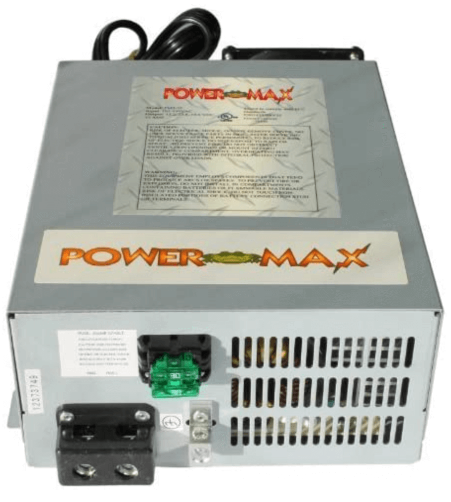
Convertor/Charger (AC-DC Charger)
A converter (aka “rectifier”) simply takes the alternating current (AC) from the grid and converts into direct current (DC). These are often times just called battery chargers.
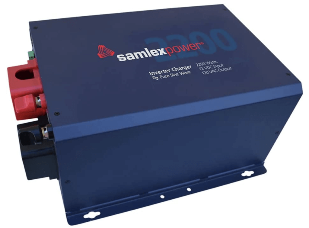
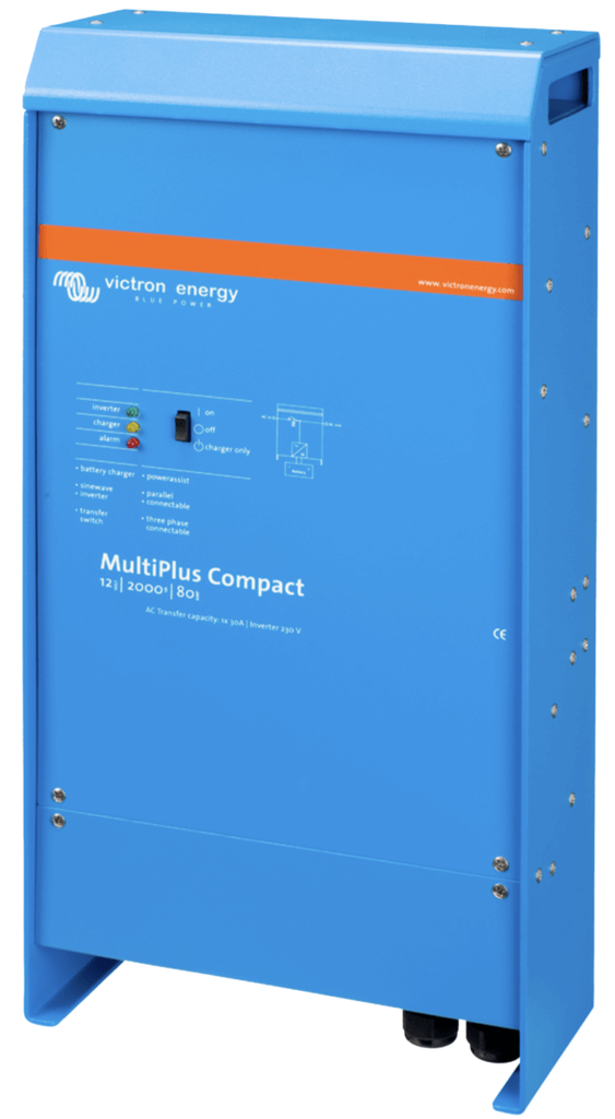
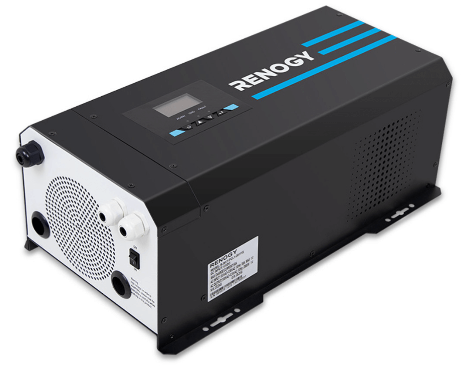
Inverter/Charger
An inverter turns direct current into alternating current. In a campervan it allows us to take the 12VDC from the battery bank and turn it into 120VAC to power typical household appliances such as microwaves, toasters, computer chargers, etc.. Inverter/Chargers also have built in converters (rectifiers) that allow you to charge from shore power. These are preferable in my opinion. We’ll discuss inverters in more detail later on.
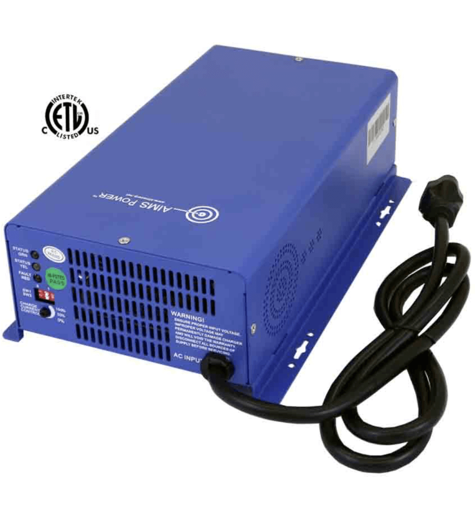
Recommended Converter
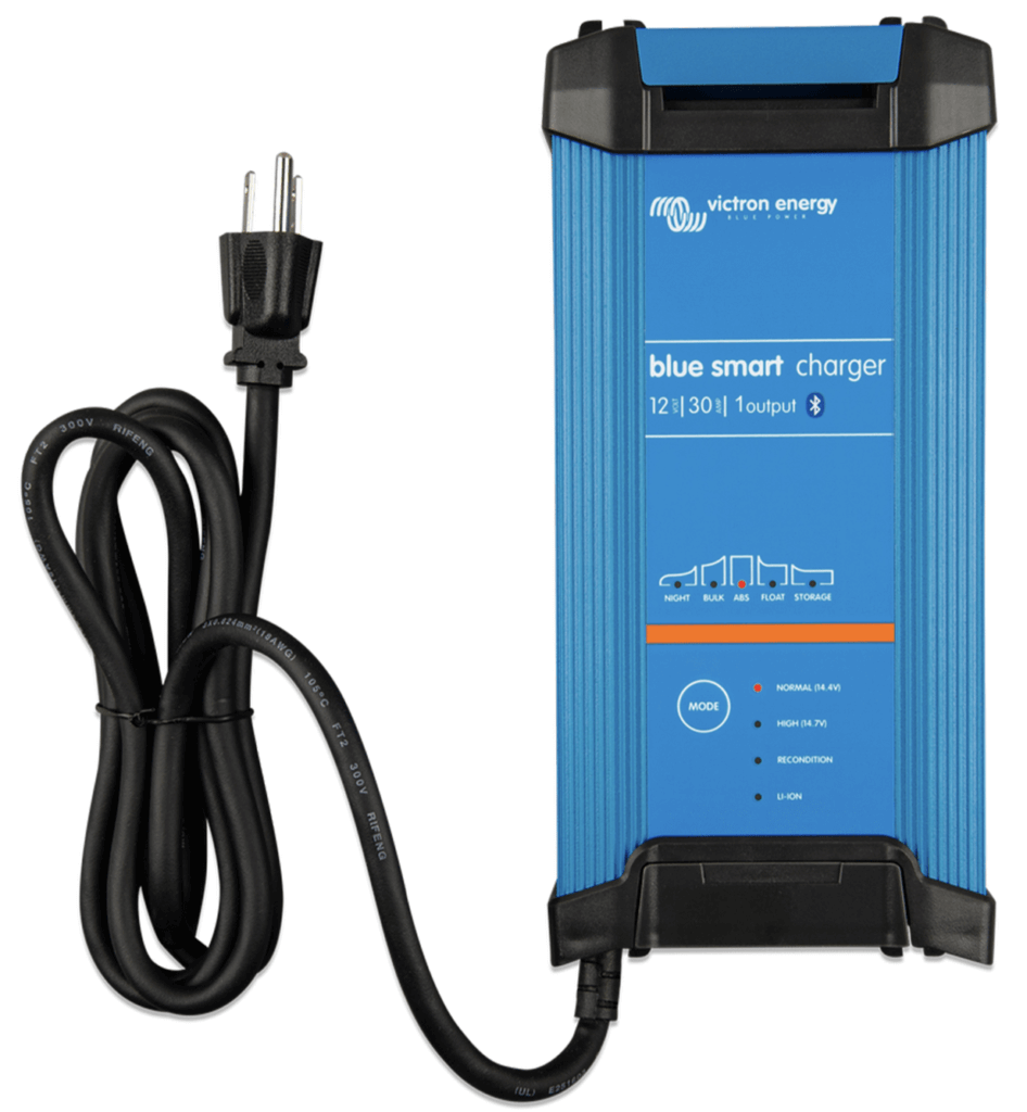
Victron BlueSmart
Key Specs
• 15A & 30A Options
• Bluetooth Built-In
Recommended Inverter/Chargers
Power Distribution and Circuit Protection
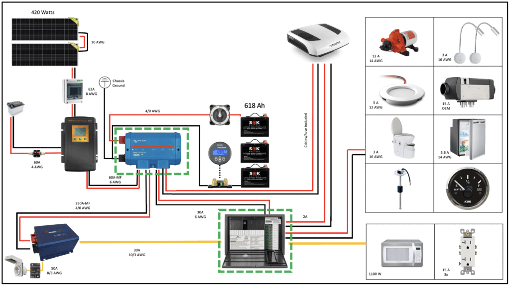
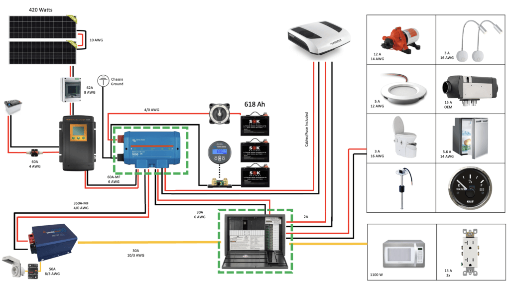
So up to this point we’ve covered a lot of items and their individual functions. In this section we’re going to look at how all of those components tie together to make one functioning electrical system. The items circled in green below will be the focus of this section. They are the: Lynx Distributor (Blue) and the WFCO Distribution Panel (Brown). These components hold the most important piece of the entire system; our fuses and breakers. Speaking of fuses and breakers let’s take a look at circuit protection first.
Circuit Protection
Circuit protection devices are designed to protect your components and yourself from the hazards associated with electricity. This items serve as the weakest link in an electrical circuit. The three items we’ll discuss here are: Fuses, Circuit Breakers, and GFCI outlets.
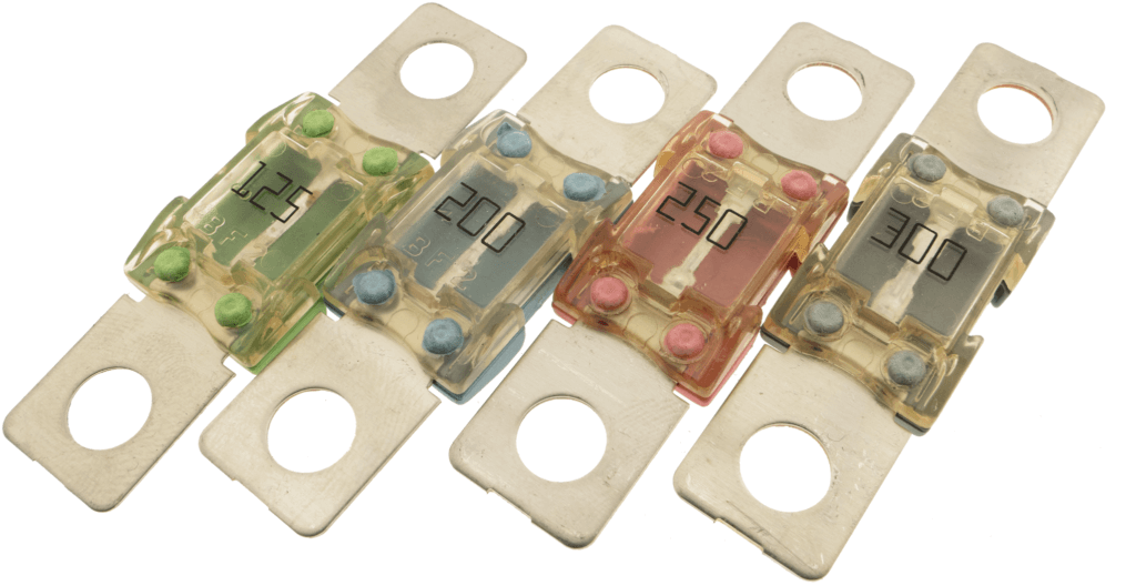
Fuses
Types: Mega (top) & Standard Blade (bottom)
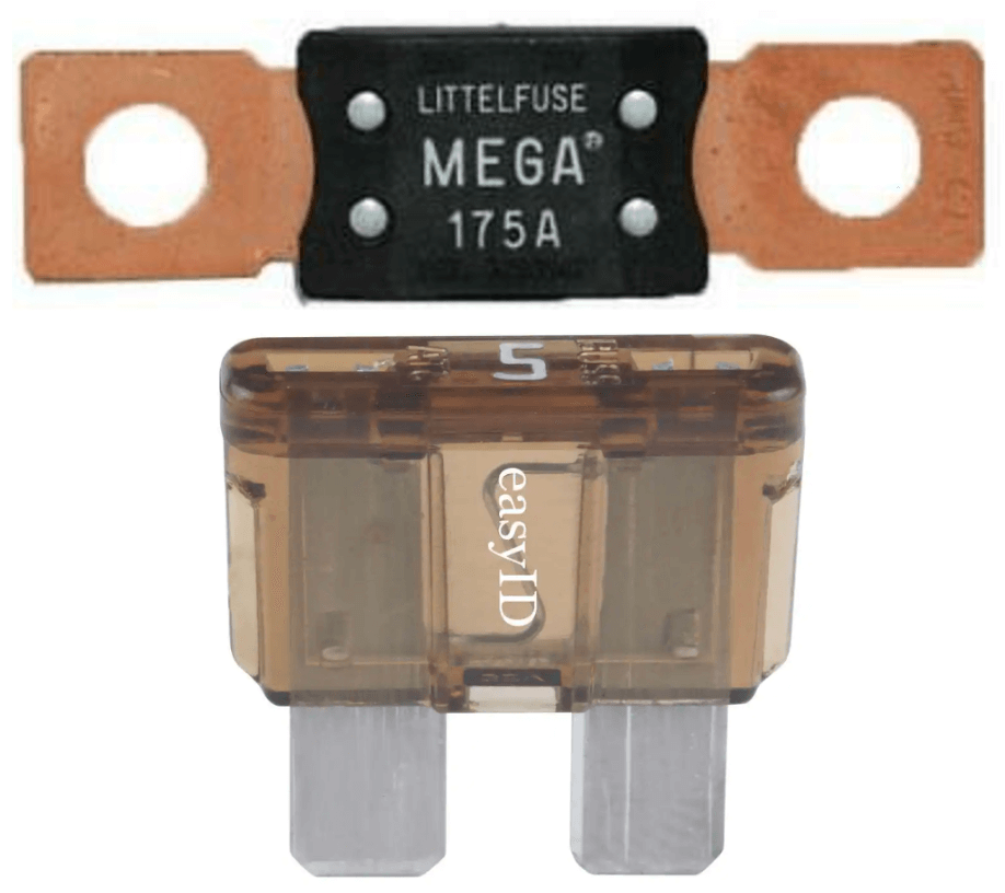
Purpose: Mega Fuses are designed to handle large current loads while blade fuses handle smaller loads.
Function: Both fuses operate in a destructive manner. In the event that a circuit exceeds the fuses rated capacity the fuse “blows” and protects the downstream loads. Once a fuse blows it needs to be replaced.
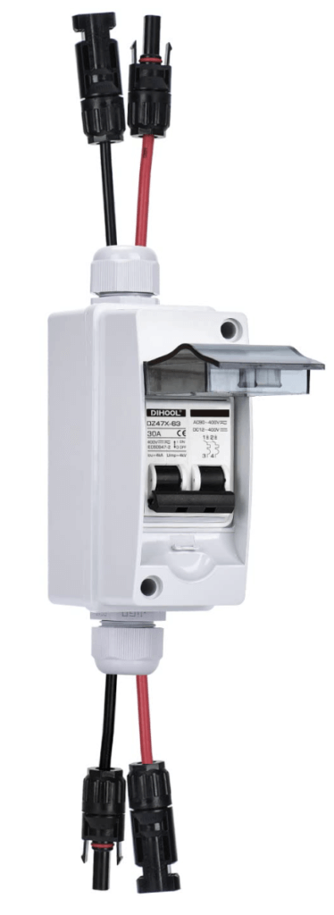
Circuit Breakers
Types: Alternating Current (left) & Direct Current (right)
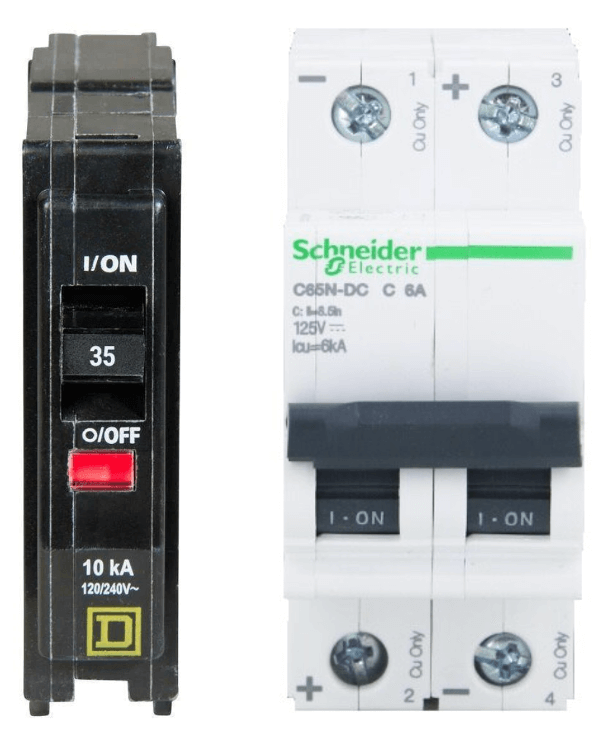
Purpose: AC circuit breakers protect AC devices while DC circuit breakers protect DC devices. DC circuit breakers are typically used for solar disconnects.
Function: Circuit breakers have a non-destructive function. When the current exceeds the breakers rating it will “trip” cutting power to the downstream devices. Once the problem is addressed you can then turn the circuit breaker back on.
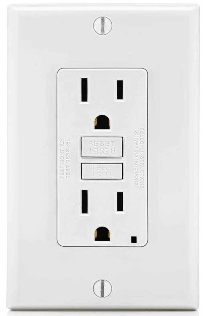
GFCI Outlets
Types: Ground Fault CIrcuit Interrupter (GFCI)
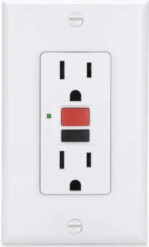
Purpose: You’ve likely seen these outlets in your homes bathroom and kitchen. These devices are the only device listed that is designed to protect the end user (you).
Function: A GFCI functions by measuring the current coming out of the outlet and comparing it to the returning current. A small difference in the returning current will trip the GFCI and keep the end user from being shocked. To reset simply press the reset button on the outlet.
** This is not a comprehensive list of circuit protection devices. I’ve only listed the devices I personally used and depend on in my vans.
Lynx Distributor
The Lynx Distributor is a high amperage DC pos/neg bus bar in one neat package. This unit centralizes most of the systems high amperage mega fuses and illuminates an indicator light if one of the fuses blows. In my system this unit houses the fuses for the inverter, DC-DC charger,MPPT Charger, WFCO WF-8930 Distribution Center, and my Dometic air conditioner.
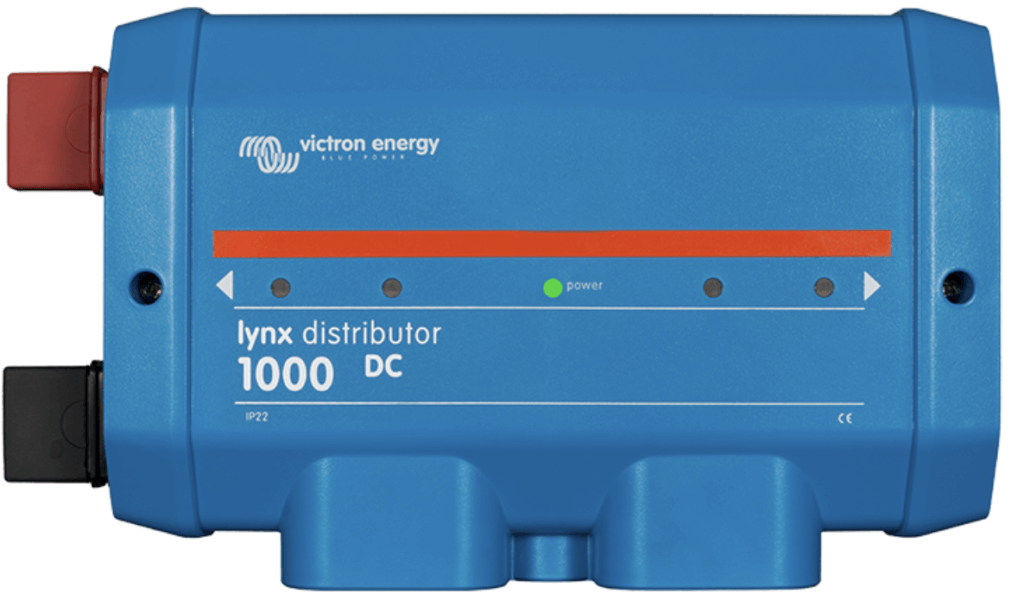
Outside View
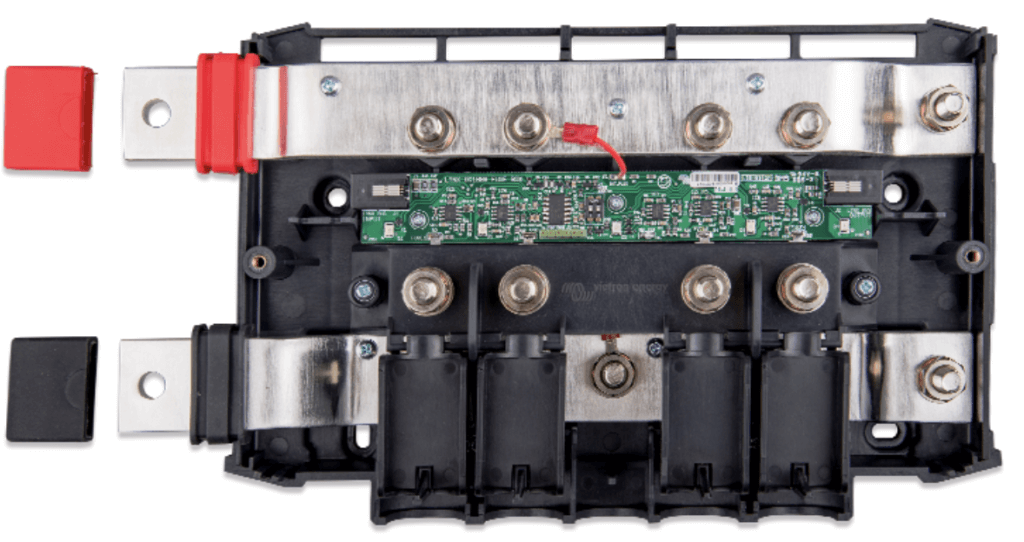
Inside View
AC/DC Power Distribution
For this I recommend using the WFCO WF-8930/8950. This unit or units similar to it are common in RV’s and for good reason. This unit houses all of your AC circuit breakers and DC blade fuses. The unit can be configured to service 30A or 50A set-ups depending on the size of your rigs inverter. It’s also very simple to wire up and keeps your electrical box in one nice and neat package.
In the example diagram shown above this unit house the AC circuit breakers for the inverter, microwave, the wall outlets; and the DC blade fuses for things like the lights, the water pump, the heater, refrigerator, etc..
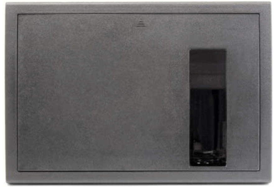
Outside View
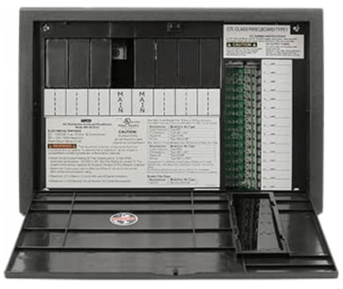
Inside View
Recommended Distribution Components
Name: WFCO-WF 8930/8950
Purpose: AC/DC Distribution. House AC circuit breakers and DC blade fuses
Recommended Fuses/ Circuit Breakers
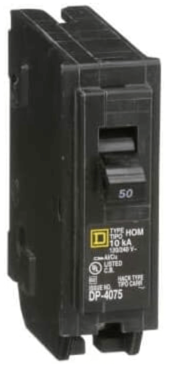
Name: Square D HOM Circuit Breaker
Size: 15A-50A
Name: Solar Disconnect
Size: 30A
*It’s worth noting that this isn’t for overload protection. This is to cut the power coming in from the solar panels when maintenance is being performed. Solar panels always produce power in the sun and do not have an on/off switch.
How to Wire your Campervan
Wiring your van is pretty simple and there’s really only a few things you need to consider: Wire size, Stranded vs. Solid, and Copper vs. Tinned Copper.
At the end of most of your wires you’ll need to connect a terminal based on the connection type. We’ll review the different types and when to use each one.
Wire Sizing
Choosing the correct size wire to connect your devices with is critical. Choose a size too small and you risk overheating the circuit and starting a fire; too big and you risk not being able to terminate the wire in the device. Let’s go over everything you need to know to make the right choice.
How is wire size measured?
Wire size in the North America is measured using the American Wire Gauge system or AWG. The system is easy to understand, but doesn’t make much sense. Regardless of my opinion this is how the system works:
- The smaller the AWG number; The larger the wire diameter.
- The larger the AWG number; the smaller the wire diameter.
So that means an AWG 0000 wire is significantly larger than an AWG 14 wire. Clear as mud!
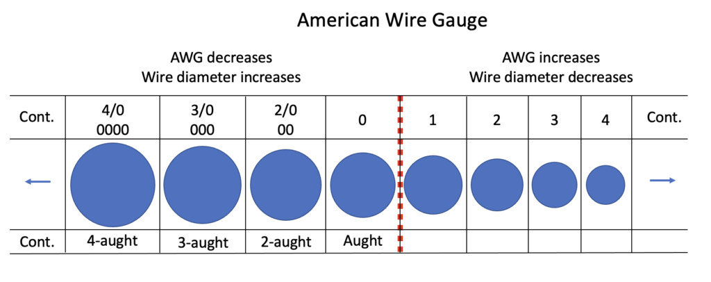
Now that we have that out of the way let’s discuss why it matters. Wires are essentially plumbing for electricity. The larger the diameter of the wire the more electricity can flow through it. However, if you you build up too much pressure in the pipe (wire) it’s going to burst (AKA start a fire). So it’s important to take this information seriously!
Voltage Drop
Voltage drop is a phenomenon that happens as current runs across a length of wire. The longer the distance of the wire the more drop that can occur. To prevent that from happening we can do two things: increase the wire size or increase the voltage. Since we’re operating at 12V then we are required to up the size of the wire accordingly to avoid prevent this from happening. There are calculations for this, but who wants to do that? Instead we can refer to a handy wire size diagram like the one below from Blue Sea Systems.
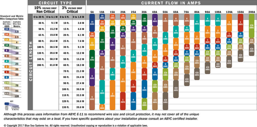
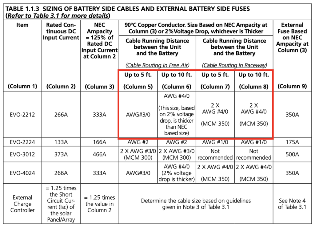
However, the best way to ensure that you are using the correct wire size is to refer to the owner’s manual of the device that you are installing. Always use the manufacturers recommendation!! Below is an example of manufacturer recommendations. This is an excerpt from the Samlex EVO 2212 manual outlining what gauge wire to use based on the distance from the battery.
Solid vs. Stranded Wire
In your home you’re likely to find loads of solid stand wiring. In a van, however, it’s important that you only use multi-strand wiring. This is because the vibration of driving can degrade the integrity of the wire over time eventually resulting in a short circuit.

Copper vs. Tinned Copper
Copper wires are cheaper, yet more prone to corrosion. Tinned copper wires are the same as bare copper, but as the name suggest they have a slight tin coating on the strands. This improves their corrosion resistance, but it significantly increases the price. In areas that aren’t going to be exposed to moisture it’s my believe that stranded copper wires are sufficient. In areas where the wire will be exposed to the elements (outside the van) then it’s not a bad idea to use tinned copper. In theory the internal strands of the wire should not be exposed to the elements anyways because the wire should have a sheathing and also be protected by split loom tubing where necessary.
Wire Terminations
Wire terminations are simply the way a wire is fixed on it’s ends that allow it to connect to a device. Terminations can be fixed to a wire with either solder or a crimp. For campervans it’s important to crimp your wires instead of soldering. Soldering creates a solid connection that could weaken due to the vibration in the vehicle. Crimping is standard in the automotive industry. My personal preference is to heat shrink every connection because it further protects against corrosion, and adds additional strength to the termination.
There is a large variety of wire terminations, but i’ll only discuss the primary ones used in campervans. The terminations below are used for connecting to devices.
Ring

Description: These are used for screw connections.
Fork

Description: These are used for screw connection too, but are easier to use because you don’t have to completely remove the screw. This is my preferred method.
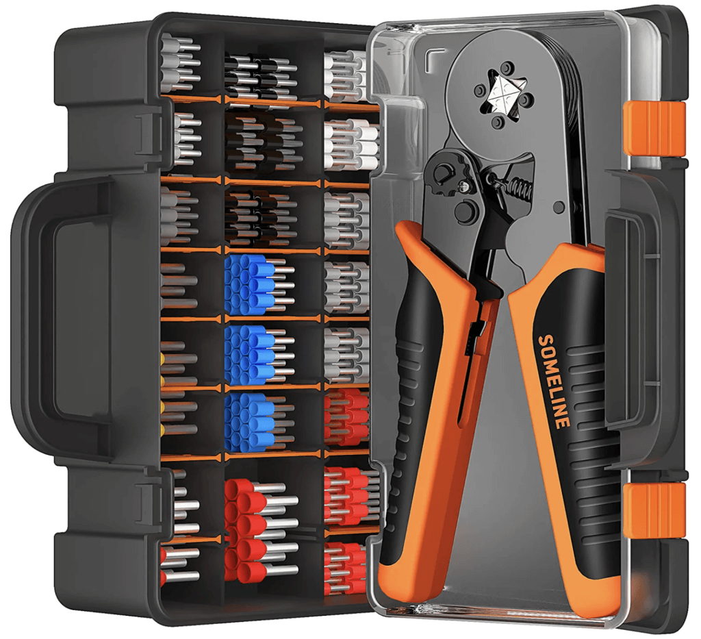
Ferrule

Description: These are used on the end of a stripped wire to keeps to loose strands neatly together. You can get by without these, but they do provide security from loose strands on the outside of your connection.
The terminations below are used to connect two wire ends together…
Closed End Butt Splice
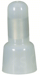
Description: These are the quickest way to connect two wire ends together. Commonly used in the RV world.
Butt Splice

Description: A cleaner more low profile way to connect two wires. These are great for wire connections that will be in conduit or split loom tubing. These are more time consuming to install because they require two crimps instead of one.
Spade
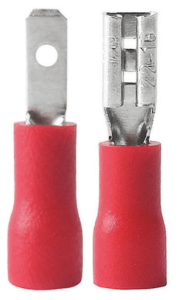
Description: These are great because it allows you to plug/unplug connections multiple times without having cut and re-crimp your wiring. Great for connections on things like lighting, switches, roof fans, etc.
Installing Wire Terminations
Wire terminations are installed by first stripping and then crimping the termination into place. I’ve linked a video below that show how to do this properly.
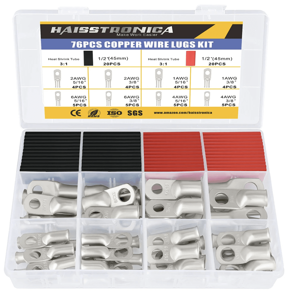
Recommended Terminations
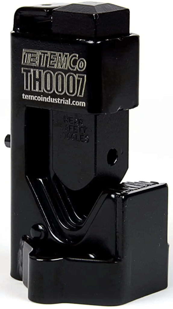
Recommended Crimping Tools
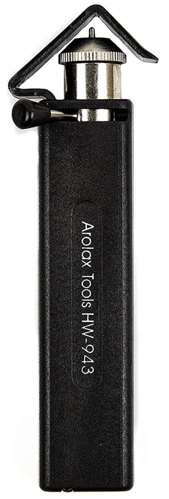
Recommended Wire Strippers
Conclusion
I know this is a lot of new information to take in at once. Don’t rush it. Read the article as many times as you need and if you have any questions please leave a comment below or reach out via our contact form. Remember, if this seems like too much work you can always schedule a consultation and let our team do the heavy lifting.
Happy building!
